![]()
![]()
Checking and Setting the Frequency of the FT1000MP REF oscillator
Abstract: The REF oscillator of the FT1000MP is used to generate the frequencies used by the radio to receive and generate signals. The dial readout is controlled by this oscillator which is nominally set to 10.48576 MHz. (Note that this implies an error of +/- 5Hz in the dial read out or the signals generated). Using simple methods and easily available software one can set this oscillator to a value of 10.485760 and reduce the read out and signal error to less than 1 Hz.
In March of 2003 I measured the frequency stability of my FT1000MP using a freeware software program called ARGO. It is available for download at www.weaksignals.com . This very nice program was written by Alberto, I2PHD and Vittorio, IK2CZL. It uses the sound card in your computer to measure the audio frequency output from the receiver when it is tuned slightly off of a carrier such as WWV. By tuning above or below the WWV frequency one will hear a beat note, the frequency of which can be measured by ARGO. ARGO can measure frequencies to the nearest HZ with essentially no error.
You can test the frequency accuracy and stability of the REF Unit in your FT1000MP by installing ARGO, connecting the AF output from the AF out jack on the back of the MP to the computer sound card mic input, and then running ARGO while listening to WWV.
I suggest the following procedure:
1. Start the ARGO program and set the parameters as follows: MODE => 3s dots, SPEED => Normal, SETUP => '0dB=ADC Full Scale', PALLETE => Darker, Visual Gain => Low. Using the slider at the right side of the screen set the frequency so that 550 is at the top right and 450 is a the bottom right. Click on the ARGO Start button and you should see the ARGO screen display move from right to left. The vertical red lines show 10 second intervals. Since your radio is off there is no signal detected by the program and the screen will be dark. See Figures 1 and 2 below to get an idea of what the ARGO screen will look like.
2. Connect an antenna that can receive WWV reasonably well to the radio and turn it on. Set the filters for normal SSB reception and quickly enter 09.999.50 MHz USB into VFO A. You should hear a tone of about 500 Hz coming from the speaker and if the tone is between 450 Hz and 550 Hz you should see a white line on the screen moving from right to left. If the line is at 500 Hz the REF oscillator is set to the correct frequency. If the value is less (or greater than 500) the difference between the white line value and 500 will be the error in the REF oscillator frequency. (550 Hz indicates that it is 50 Hz high, 460 Hz indicates it is 40 Hz low).
In the event that you do not see a white line try tuning the VFO A dial either up or down until the tone becomes lower and eventually is zero beat or disappears. Now move the VFO either 500 HZ up or 500 Hz down until you see the white line appear on the ARGO screen. Remember, there is some latency between the screen and the tone at any instant so move the dial relatively slowly.
3. Once you have located the white line on the screen you can determine the REF oscillator error. Except in very unusual cases the error will be small -- a few tens of cycles. Look at the frequency readout of VFO A. and add to it the frequency value of the white line (in Hz ). Subtract 10.000000 MHz the sum . The result will be the error in the setting of the REF oscillator.
For example, if your VFO A is at 9.999.50 MHz USB and the white line is at 460 Hz the sum will be 9.999960 MHz. Subtracting 10.000000 MHz from this gives us an error of - 0.000040 MHz or 40 Hz.
4. Once you are certain that you have a setting of VFO A that allows you to see the white line, turn off the radio and let it sit for at least 15 minutes. Then start ARGO and turn the radio on again. If the REF oscillator drifts (expect it to do so) you will be able to see the drift in HZ as a function of time. The white line will move up as the frequency changes ( I am assuming that there will be positive drift in most cases). You may wish leave the radio on for an hour or so and see where the frequency drifts to..
Figure 1 below shows the cold start characteristic of my FT1000MP after I added a thermistor compensator. Figure 2 shows the same radio after a long warm up period.
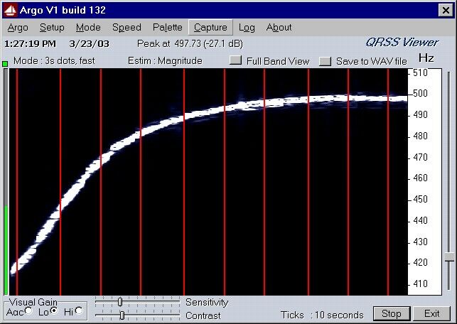
Figure 1 shows the cold start drift over the first 90 seconds of operation. In this
case it is about 80 Hz and the absolute error is 2.27 Hz. (0.227 ppm)
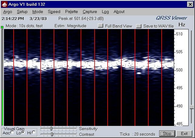
Figure 2 which shows the REF oscillator is 1.64 Hz off the desired frequency
or about 0.164 ppm.
If the REF oscillator frequency is off you can correct it by taking off the top and bottom covers of the radio and locating the REF oscillator on the right front side of the radio. Figure 3 below shows what you should see.
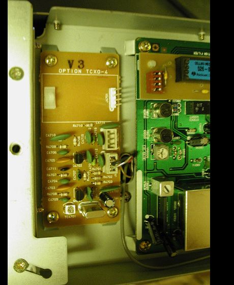
Figure 3
You will see a small trimmer capacitor (TC4701) on the lower left corner of the REF oscillator board that is used to adjust the frequency. To make the frequency adjustment turn the radio so that the right side is up and the trimmer is easy to see. Turn on the radio and set VFO A for 09.999.50 MHz USB. Start the ARGO program and locate the white line. If the white line is NOT in the range of 400 to 500 HZ, very carefully adjust the trimmer capacitor in small increments until the white line appears on the screen. Once the white line is on the screen, adjust the trimmer very slowly moving the line to exactly 500 Hz on the screen.
Let the radio run for at least 30 minutes and adjust the frequency again to 500 Hz if it has changed.. Very tiny changes in the trimmer position will produce relatively large changes in the frequency when you are within 1 or 2 Hz of the correct value. Determine which direction of trimmer change moves the frequency up and which moves it down. Make a note of the direction. Tune until the accuracy suits you (if you are lucky or casual this will happen quickly, if you are picky plan to spend some time getting just what you want).
Now replace the covers of the radio and once again go through the measurement process using ARGO. If the frequency with the covers on is too far away from what you desire, write down the difference (pay attention to whether you need to go up or down in frequency) and once again go through the adjustment process. This time adjust the frequency to be slightly above (if it was too low) or slightly below (if it was too high) 500 Hz by the amount that you wrote down when the covers were on. After this has been done you when you restore the covers to the radio the frequency should be very close to the desired value.
If your REF oscillator drifts (too much) you may wish to install the simple temperature compensation I did using a thermistor. That installation is at the Temperature Stabilized FT1000MP REF oscillator note elsewhere on this web site.
Tod Olson, KØTO
![]()
![]()
![]()