![]()
HyTower Leg Insulator Failure
************ Please read to the end of this note where you will see the repair that I made.
************ I believe the cause of failure was (1) the material used in 1975 and before to make the insulators and (2) small cracks that permitted water to permeate the insulators and then generate steam due to dielectric heating which in turn exploded the insulators. I have since replaced all of the insulators and operated at the same power levels in all of the 2006 DX, 160 meter and ARRL SS contests with no problems.
-------------------------------------------------------------------------------------------------------------------------
On January 29, 2006 during the last 15 minutes of the CQ 160 CW contest I got a sudden ACOM 2000A fault indication. It proved to be a problem with the feed line input impedance for the modified HyTower is use as a vertical antenna on 160 and 80 meters. Matching networks for each of the bands are switched by vacuum relays controlled at the station.
My HyTower has been modified so that it no longer has the physical and electrical characteristics of the standard HyTower. The "stinger" of my HyTower is NOT insulated from the main tower body as is the case in the regular HyTower installation. Instead it is deliberately shorted to the tower at the top where the stinger is clamped. In addition, my HyTower has a 45 foot long wire connected to the stinger and then stretched horizontally to provide top loading to the antenna. In summary, my HyTower is a 52 foot high top loaded vertical insulated from ground . Power is fed to the base of the HyTower at the normal point. The antenna is slightly shorter than a 3/16 wavelength on 160 meters and slightly longer than 1/4 wave on 80 meters.
On 160 meters a high Q L-network consisting of a shunt coil and a series coil is used to tune out the reactance and step up the resistance to a nominal 50 ohms. The SWR from 1800 to 1900 kHz is less than 4:1 .
On 80 and 75 meters the two 160 meter coils are connected to provide a single shunt inductance to ground and serie capacitors are selected by relays to cover either the CW portion or the SSB portion of the band. The SWR from 3500-3600 is 1.6:1 or less and from 3750-3875 it is 1:7:1 or less . Since the feed to the vertical is done with 7/8" CATV no attempt is made to reduce the SWR further at the tower base.
At the station, separate L-networks are switched in and out to provide 1.5: SWR over the 1800-1840 and 1840-1880 band segments. The SWR on 80 and 75 requires no additional matching.
The pictures below show the insulator failure as photographed the day after the Contest. After those pictures are some pictures of a spare base insulator and after that some insulators I plan to install to replace the current set of insulators. This is the second time in two years that an insulator has failed. This time, however, the failure is much more dramatic than the first one.
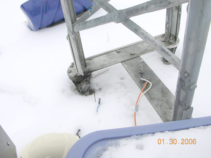
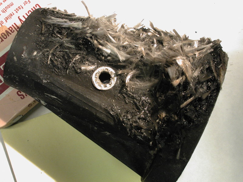
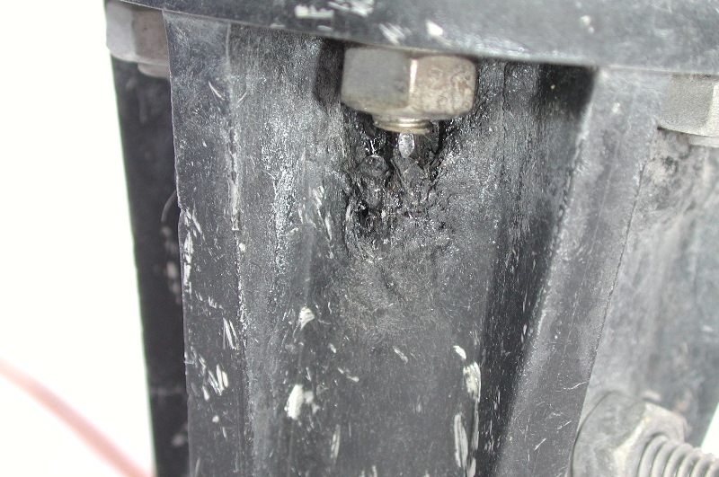
The Blue Box shelters the Matching networks for the base of the tower. The orange wire is the feed from the network. The tower leg in the left center of the photo is the one which has the failed insulator. Notice the "feathers' from the fiberglass that is imbedded in the molded insulator.
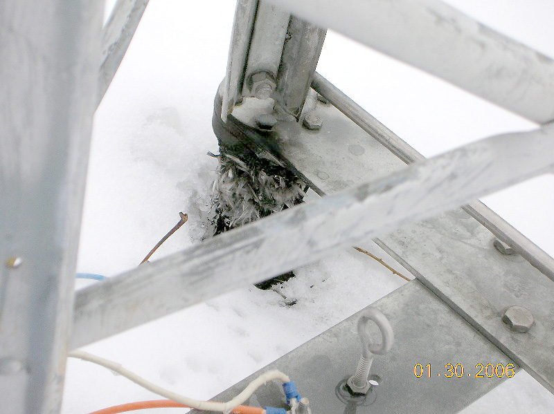
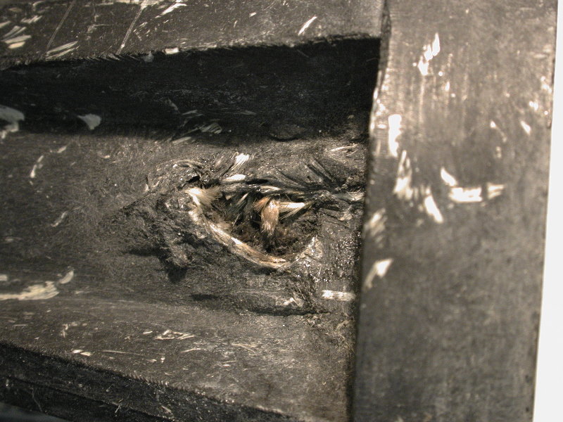
This photo provides a closer look at the failed insulator.
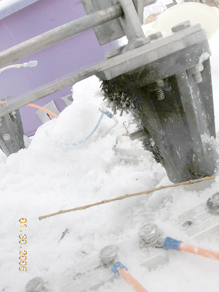
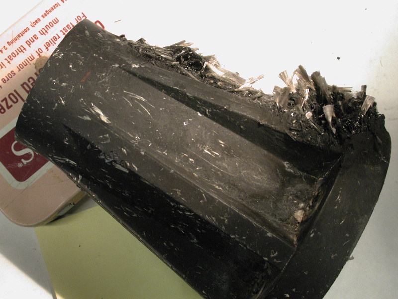
A view from the side opposite to the matching network.
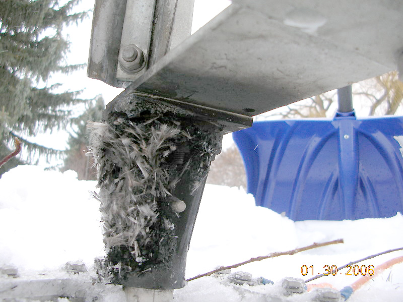
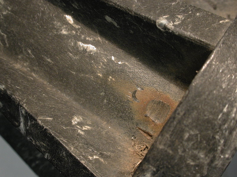
A close up view looking under the Tee base. There is significant blackening of the metal which may indicate that the insulator caught on fire at some point. There is a polystyrene shim between the top of the insulator and the metal bracket. This shim makes the tower vertical rather than having a small amount of tilt.
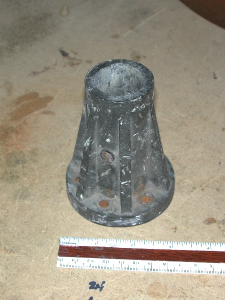
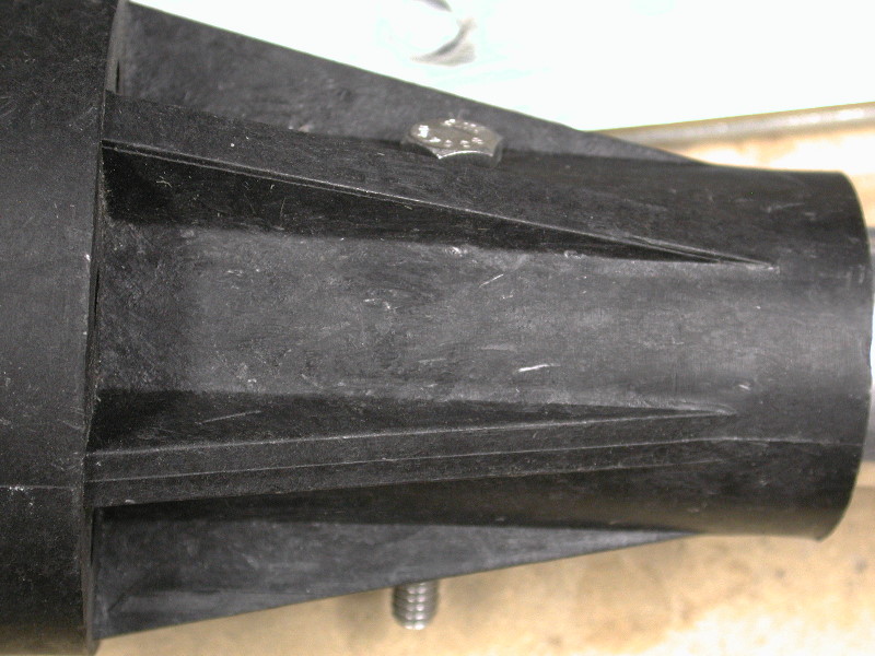
The next pictures show a spare insulator so one gets and idea of how the insulator looked originally and how it is installed. This insulator, and the ones that were in place, are quite ancient -- perhaps 20, maybe even 25 years old.
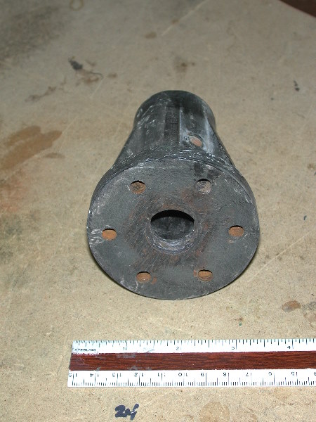
Insulator Autopsy.
On February 5, 2006 I tilted the HyTower over so I could remove it from the base mounting plate and get access to the three base insulators. After chipping away the ice that had frozen over the bolt heads holding the insulators to the base I was able to remove the six 1/4-20 x 1-1/2" bolts. Then it was necessary to heat the insulators sufficiently to melt the film of ice that held them tightly to the vertical tubes going into the cement base. Since the temperature was a balmy 20 degrees F and the wind was only blowing at 25 mph I was able to do the job with only one trip into the house for a hot chocolate fix.
Once the insulators were removed I took them into the shop and examined them. I also found the insulator that had failed two years ago and a second insulator that was of the same vintage as the insulators removed. Finally, I took a couple of pictures of new style of base insulators (vintage 2002) so I could compare them with the removed ones.
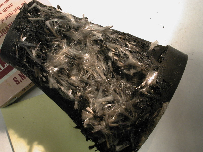
The next six pictures show the insulator destroyed Jan 29,2006.
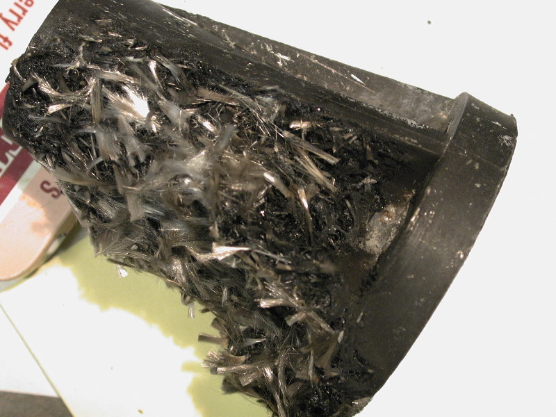
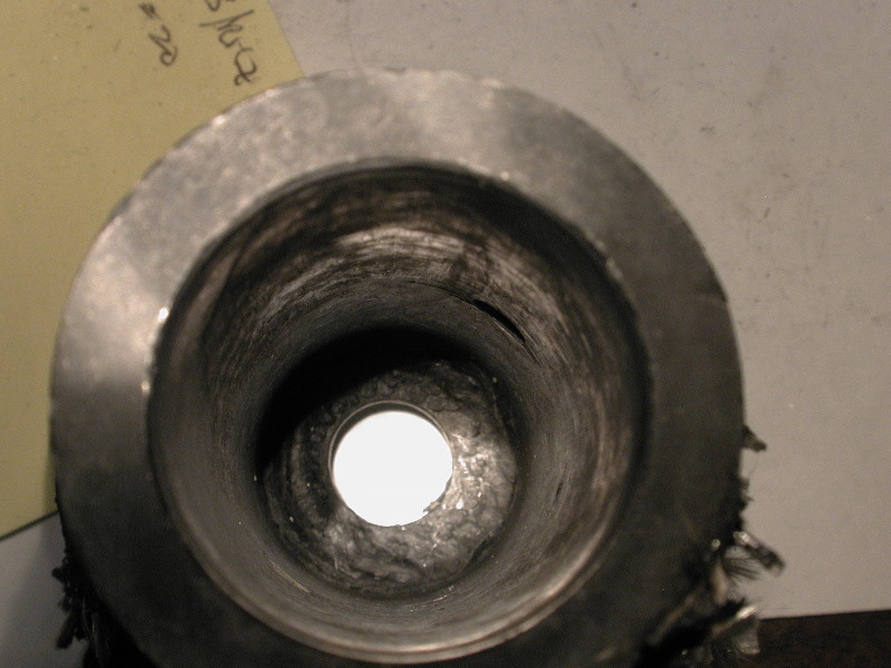
Looking down the inside of the insulator there was no indication of any breakdown or puncture.
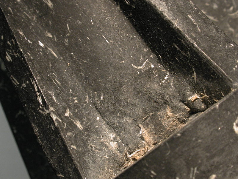
The next pictures are from the part of the insulator that did not fail. Note the deformation of the epoxy material in the vicinity of the point where the bolt comes through the insulator and the nut is located. This change in material was noticed both in the first failure and in the second failure.
The next two pictures were taken of the insulator failure in 2004. The first one was taken with the insulator in place and shows the damage which appears to be a puncture of the insulator area that separated the nut from the vertical tube going into the concrete base.
The picture below was taken after the insulator had been removed from the tower and replaced with one that was of the same vintage ( circa 1975). The puncture is very apparent and when examined very closely it appeared as though there was a carbon path along the fiber imbedded in the epoxy.
After some consideration I decided to replace all of the base insulators with new ones ordered from MFJ (HyGain Division). A picture of the new insulator is shown below. The material seems to be different from that which was used in the original insulators.
The new insulators were placed in service in time for the CQ 160 meter SSB contest and the ARRL DX Contests that followed. Once again I used my ACOM 2000A amplifier with 1.5 KW output and as of March 14, 2007 there have been no further base insulator failures since the original problem.
comments and suggestions are always appreciated. Send comments to
Tod Olson: tod@k0to.us