![]()
![]()
Making MFJ-259B Test Point voltage measurements
I am asking the assistance of others to develop a set of data that can be used to determine if the diodes of an MFJ-159B have been damaged. If you are willing to carry out some simple measurements and share your data I would very much appreciate it. If you have any concerns about damaging your MFJ-259B while making the measurements you should NOT participate. I do not feel there is much risk of damage but there is always a chance something will happen once you open the case of any device and probe voltages inside the device. I will not accept responsibility for any units that might be harmed by the procedures below and you should not participate if you are not willing to accept responsibility for anything that happens while you are performing the measurement procedures.
PLEASE READ COMPLETELY THE INSTRUCTIONS BELOW BEFORE STARTING THE MEASUREMENT PROCESS.
[If you can print out the instructions for use while performing the procedure it might be helpful.]
1. To make these measurements one must have a digital voltmeter that will measure millivolts or at least 0.01 volts. The measurements require that you remove the back case of the unit and also the battery holder. It does not require that anything be unsoldered.
2. You will need test loads. You will need a coax plug which has the center pin grounded [an R=Zero load] and a 50 ohm Load -- preferably a commercial one or a 1/4 carbon film resistor going from the center pin to ground on a PL259 plug. The objective is to have an R=Very High load [open circuit], a R=Zero load and an R=50 ohm load for the MFJ to measure.
3. The unit with should be operated with voltage supplied by an external regulated supply -- not the wall wart type. An alternative is to use batteries in the battery holder as the power source. The battery holder needs to be positioned so that there is no contact with the PC board of the unit. Also, if you spend a long time making the measurements [not really necessary] you may drain the batteries .When you turn on the unit you should hold down the MODE button while pressing the POWER button. This will disable the "Power Saving" mode and keep your measurements from being interrupted.
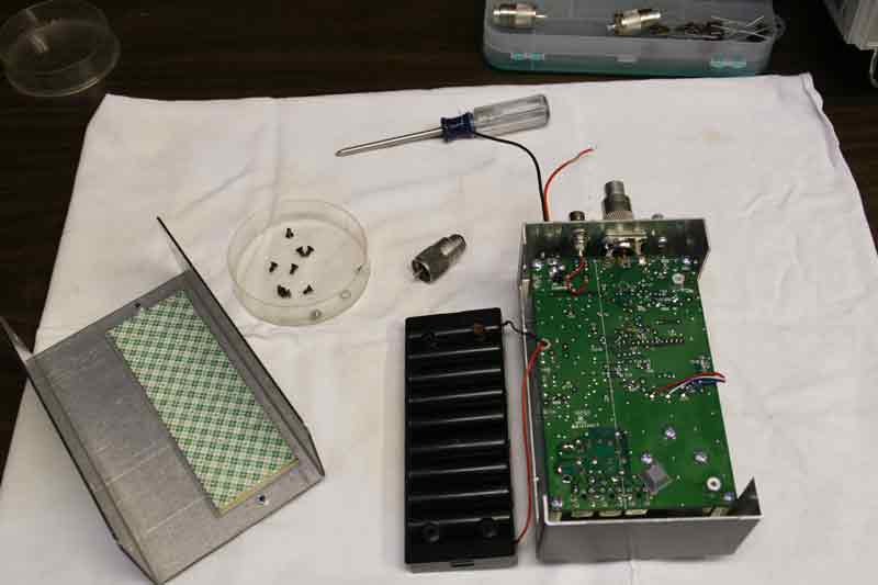
4. Place the MFJ-259B face down with the coax jack away from you on a towel or soft material. Have a small container available to hold the 8-case screws and 2 battery holder screws
5. Carefully remove and save the four screws on each side of the MFJ case and remove the back of the case. This will expose the battery holder. Remove ALL the batteries. Then remove the two shiny metal screws that are closest to the outside edge of the case. Lift out the battery holder and place it at the side of the unit face down on the left side of the unit.. If you plan to use batteries to run the unit during the measurements re-install them now and position the holder so the batteries are facing down. This should minimize the strain on the battery leads. The picture above shows how things should look when you have the unit ready for measurements.
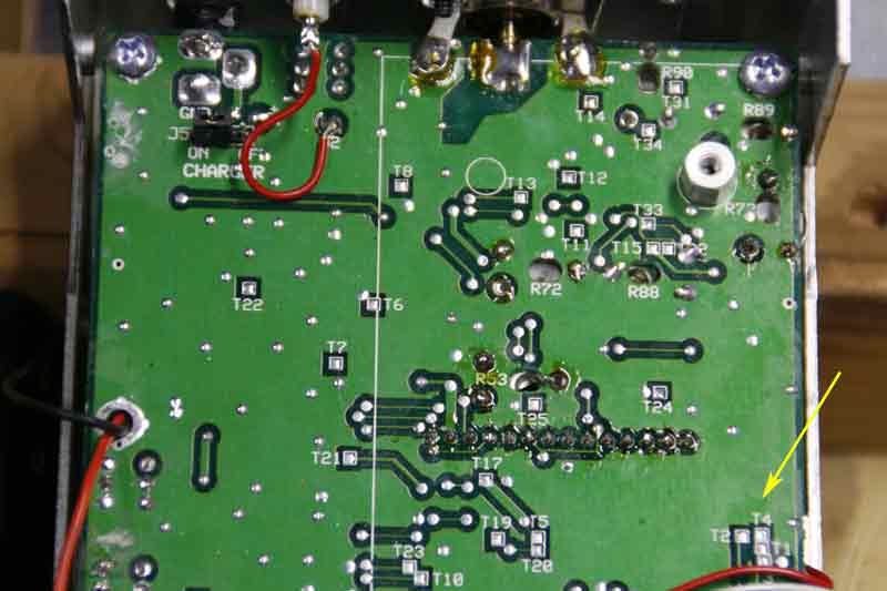
6. Using the picture below locate the four test points T11, T12, T13 and T14 below and to the right of the coax jack at the top of the PC board. The test points will be small squares of solder.
Using the same picture locate the closely spaced test points T1,T2,T3 and T4 at the lower right side of the picture [yellow arrow]. There are red, black and white wires running just below these test points.
When you measure the voltages on these test points be careful not to touch other points on the board.
7. Turn the MFJ-259B on and set the frequency for 10.00 MHz [close is OK] . Reposition the unit to be face down with the coax jack at the top.
8. Connect the ground lead of your DMM to one of the ground lugs of the coax jack. Using the positive probe of the DMM carefully measure the DC voltage present on the four test points T11, T121, T13 and T14. Write down the value after each measurement .
9. Using the positive DMM probe carefully measure the DC voltage on test points T1, T2, T3 and T4. Write down the value after each measurement.
10. Insert the R=zero load into the coax jack. Repeat the measurements made in steps 8 and 9 above. Make sure that you indicate these measurements were made with the R=zero load.
11. Remove the R=zero load and insert the R=50 ohm load. Once again repeat steps 8 and 9 above. Make sure that you record the fact that these measurements were made with the R=50 ohm load.
12. Transfer all of the measurements you made into the MFJ-159B Measurements Form below and then click on the Submit Measurements Button.
Thank you for participating in collecting these data.