![]()
![]()
Here is a quick review of my work installing the W8JI key click mod.
If you have not already done so look at these URLs. The first one is for the FT1000MP; the second is for the Mark V. Look at both since the boards of the two radios are very similar and you will get a good idea of what you are looking for when you see the boards.
http://www.w8ji.com/keyclick_mp.htm
http://www.w8ji.com/ft1000mk_v.htm
Also check the www.va3cr.net website for additional pictures and notes.
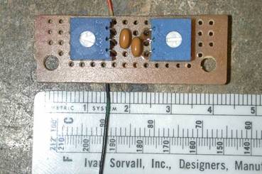
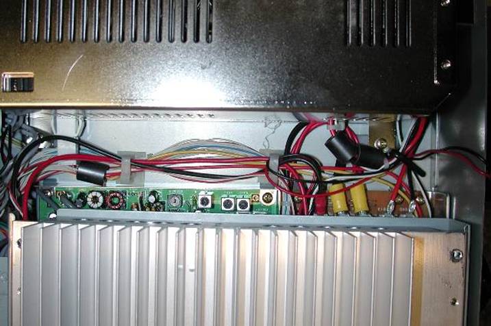
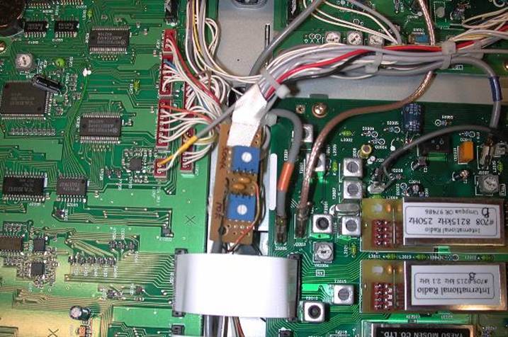
The picture below shows the
small board that I built to hold the capacitors and the pots the are connected to
points on the Filter Board. As I recall I used 470K and 15 pots for R1 and R2
respectively. Unfortunately all of my exact value information is in my lab
notebook in
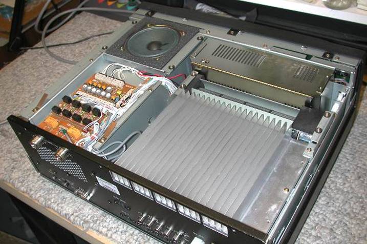
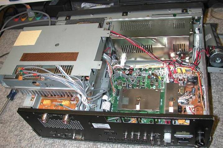
The next pictures show getting to the RF board where you install one capacitor. You remove the covers and look at the top of the radio. The lower right shows the heat sink and the center is the fan. The URL references will give step by step instructions which should be printed out for reference before you begin the process of doing the work.
Remove the fan and set it alongside the radio..
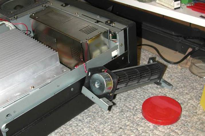
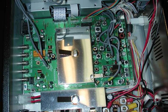
Then you unclip the plastic tabs that hold the cables and remove the heat sink mounting screws and flip up the heat sink to get at the RF board.
Flip the heat sink to the left side to expose the RF Board..
This is a view of the RF board.
Remove all of the mounting screws that hold the board and carefully lift it so you can get at the backside of the board.
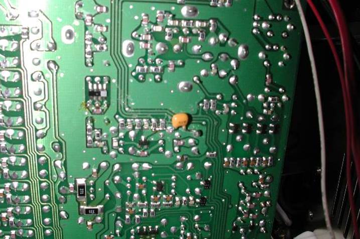
This is what you will see when you look at the backside of the board. . The capacitor on the top right side is the one I added. Note that the three little chip capacitors (left of the added cap) are connected together giving a easy point for that connection.. The right side lead is easy to place.
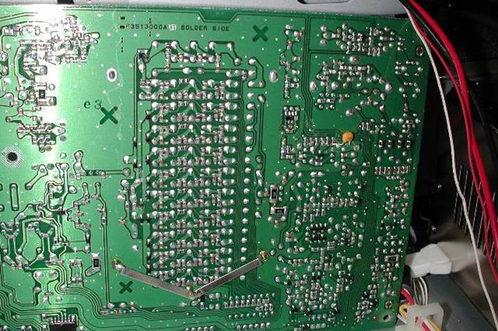
This is a close up of the location where the capacitor on the RF board goes.
After installing the capacitor, put the RF Board back and restore the cables and the heat sink so everything is as it was.
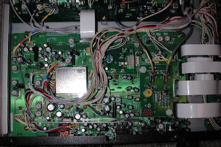
Then turn the radio over and find the IF board and the Filter Board. The picture below shows the board with the INRAD IF mod in place. That was removed later and the Roofing filter mod installed in the same space. This is NOT the board that is involved with the key click mod.
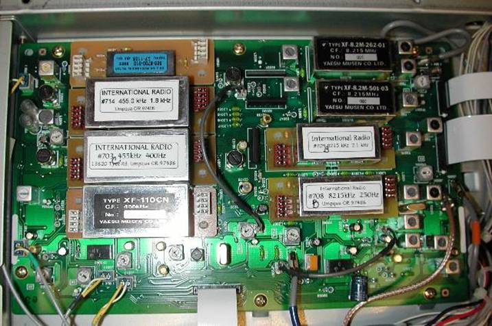
The picture below shows the filters installed. This is the board that will have the rest of the key click mod work. The ribbon cables at the right are the ones you will need to remove so that you can get at the back of the board.
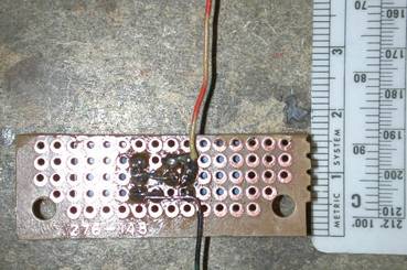
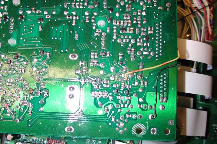
Next remove the mounting screws and flip the board. Notice where I put the black (ground) wire from my little perf board. The yellow orange wire is the one that goes from the junction of R1 and C1 in the w8JI URL reference above to the capacitor. Look for the very distinctive trace. The wires wrap around the edge of the board and go to the perf board.
The picture below shows where I mounted the small perf board. I used glass tape because I had some. I would have preferred to use some small Velcro tabs or some of the foam sticky tabs, but did not have them on hand. The board is mounted on the cable bundle that runs along the left side of the filter board as viewed from the rear of the radio. This picture was taken so that the front of the radio is at the bottom and the back of the radio is at the top.
The two pots are conveniently placed so you can adjust them. Be alert to the fact that the correct setting is somewhat sharp and may take a bit of back and forth adjusting between the two pots to get the clicks reduced so that they are at least 30 dB down within +/- 500 Hz of the transmit frequency. Reducing them substantially is an easy adjustment; reducing them the best you can for your radio takes a little more time. However, once the adjusting is done you will not adjust it again so the time spent is well worth it.
I used about 70 dB of attenuation which had input and output impedances of 50 ohms between the output of the MP and the input to my second receiver (IC-706) to prevent it from being fried. The output of the MP was sent to minimum which produced a signal of S9+40 dB or so in the ICOM. If you don’t have attenuators you probably should transmit into a dummy load and see if you can’t get enough pick up from a small wire as the antenna of the second receiver. DO NOT CONNECT THE FT1000MP DIRECTLY TO A SECOND RADIO WITHOUT ATTENUATORS IN SERIES WITH THE CONNECTION !!!!
If there are questions you may contact me via email.
Tod Olson, KØTO
![]()
![]()